Servo motors are proposed for low speed, medium torque and accurate position application. 4. now it is the turn of servo motor number 3, we leave the position of the servo motor at 90 degrees in this case and we mount the arm in alignment with the next one, as this gives us 60 degrees of movement in each direction. This would help build an index of different versions and functionalities of the Robotic Arm. I saw that the arduino code is present but not the diagram. Submitted by AISHA on Thu, 05/03/2018 - 07:34, In reply to ASKING THE QUESTION by MANDLAH, Just make sure the motors dont consume more power. picks an object, detects whether the object is metal/non-metal, and sorts it by placing it at different angle displacements? I would be appreciate a lot.  The NEMA-17 and the A4988 Driver si used to control the direction of the Motor, you can see from the diagram below: And finally, the following diagram shows the final wiring diagram assembly of the complete Robotic Arm. Which book best for preparing project by using arduino,microcontroller, which help me make to project by my hand!!! The main thing that each servo has to provide torque for is to counteract the moment caused by the motor on the end of the arm which it is moving. Hi Michael, seems youll need to use the 180 degrees Servo Motor versions (the one used for this Arm). The Robotic Arm code can be found on GitHub. More interesting projects on the way. The code has already been documented (Also available on Git). There is a list of different Robots that use servo motors, so the theory of what were building still applies.
 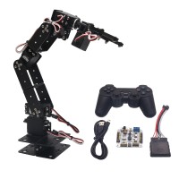 Make sure the piece is not softened. Submitted by Ameer Ul Islam on Mon, 03/26/2018 - 14:21. what is the voltage range required for the capacitors In this case we get the 120 degrees that the MG995 works with. In this tutorial,we are going to design an Arduino Uno based Robotic Armfrom some cardboardsand servo motors. /********************************************************************************************************, * *, * This sketch controls the servo motors of the robotic arm. i cant find hcpca9685 library . This helps in the long run, as there are many examples of a 3D printed robotic arm that can be customized, e.g., adding an LED, creating a camera stand Clamp: As previously mentioned, the Robotic Arm was modeled around the Robotic Arm on Thingyverse. This project will be helpful for beginners who want to learn to develop a Simple Robot in low cost or just want to learn working with Arduino and servo motors. Here we start with the settings for each of the servo motors that need to act to execute the movement. For the other stages, the adaptation method is similar. In keeping true to the Robotic Arms aesthetics, you can print a 3D Printed Exoskeleton Gauntlet to use as your Robotic Glove. As I noticed the code which you placed at Github should be adjusted before using. Adafruit_PWMServoDriver pca9685 = Adafruit_PWMServoDriver(); The next 4 lines are in order the implementation of an Adafruit_PWMServoDriver object to control the servo motor positions. Semicon Media is a unique collection of online media, focused purely on the Electronics Community across the globe. You can move these servos by rotating the pots to pick some object, with some practice you can easily pick and move the object from one place to another. This project is an attempt at achieving this. So for every (5/1024= 4.9mV) per unit. This statement maps both values automatically and stores the result in integer servovalue0. Are you using a continuous servo? Servo motor 5 is the one that rotates the robot arm. mapping the voltage levels using ADC channels in Arduino here. Current version does not work. The Robotic Gloves Arduino uses sensors to communicate with the Robotic Arm Arduino and sends data to move a Servo to the desired angle. We have the microcontroller, the PCA9685 module and the 6 servo motors. Should Adafruit driver be the same as HCPCS9685, Hi Trevor, We have used low torque servos here but you can use more powerful servos to pick heavy objects. Keep in mind to wear the glove before turning it on as this would take the initial reference position. Submitted by Mrinal on Sun, 04/01/2018 - 23:52. Hello, The SERVO header (Servo.h) file takes care of all the duty ratio calculations internally. According to the data sheet, the MG995 servo motor rotates 120 degrees, while the MG90S and SG90 servo motors rotate 180 degrees. Servo motor 5 is the one that rotates the robot arm. Submitted by Inam Ulla on Thu, 03/02/2017 - 21:29, Submitted by R. Sudar on Mon, 12/27/2021 - 22:03, In reply to Will this project work by Inam Ulla, Submitted by kutaiba ahmed on Wed, 03/08/2017 - 06:07, nice work , i really liked the idea I am very impressed by this project and plan to give it a go. You can access Wonder Tigers Robotic Arm from the Parts list. The Arduino Robotic Arm communicates over Bluetooth using the HC-05 modules. Second statement is naming the servo; we leave it as servo0 as we are going to use four. I have a 3D printer so that helps. Note: The code implements a hard stop to stop the Motor from exceeding its maximum angle, which can strip the motor gears. The following two functions execute the movements of servo motors 3 and 2. Now glue the fourth and last servo at the edge of second piece as shown in figure. Now, for the UNO to convert analog signal into digital signal, we need toUse ADC Channel of Arduino Uno, with the help of below functions: Arduino ADC channels have adefault reference value of 5V. In this project, a 5V, a 2200 mAh RC Battery was used. are the rising edge and falling edge values for the 0 degree and 180 degree position of the servo motors respectively. Ive updated the post to include the link to the library. You can pretty much then start from Arduino and programming building. Wire.h is for I2C communication and Adafruit_PWMServoDriver is for using the PCA9685 module.
  how can i make it repeat the work alone without the interfare of the pots But I have several problems with it. You could use a 9V battery, but the capacity would not be as much(assuming youre referring to the 12V NEMA 17 Motor) Would it be possible to build a small robot arm with simple electronic modules and components? We have used four for our Robotic Arm. All rights reserved. This is an Arduino Robot Arm that can be programmed or even controlled by Hand Gestures. Say if we want the servo to be at 30, we can directly represent the value in the program. Then fit the third servo in the first hole. If the flex sensor goes above or below this value, data is sent to the Robotic Arm to move a specific servo motor in a specific direction. However, the parts could take a collect at least 40 hours to print all parts. For the operation of our robot arm it is very important to know the pulse width data of the servo motors in order to position the minimum and maximum angle with the adjustment sketches and to bring the robot arm into the desired position. These are not proposed for high speed applications. Well constantly check if the current value has exceeded the defined flexs upper or lower limit based on the calibration. The second is to send the PWM signal to the respective servo motor, which was transmitted via the I2C signal from the microcontroller. With the function, we tell the PCA9685 module to move motor 5 to the position resulting from subtracting the value of the rising edge (0) from the falling edge (350), and with the function. ) The development of the last two functions that move servo motors 1 and 0 (gripper) is similar to that described above. These industrial robots have powerful motors and special electronic circuits to control movements according to programmed coordinates. Purchasing a Robotic Arm can be quite expensive. Suppose if they do make sure you power supply could source it. method we initialise the serial monitor and output a message. Lastly, Were also able to control the Robot through hand gestures and program the Robot to automate basic tasks. In simulation we can'tgive power and ground connection to arduino uno. This way we can check which coordinates are correct in which positions and we can adjust the values of the variables pos of each servo motor so that the robot arm is positioned at the desired coordinates. The prepared sketch robot_arm.ino executes a path that starts from a safety position, moves two parts and returns to the safety position. Amazing job Dilip. Stay tuned! View the Full DIY Robot Arm (controlled by Hand Gestures) Tutorial Here. executes a path that starts from a safety position, moves two parts and returns to the safety position. When we attach this setup to the base it should look like. The actual arm itself will have a very negligible effect on the moment here because it is on such a small scale. Submitted by vishal vhatkar on Wed, 04/19/2017 - 22:31, the wholw setup of project is very nice I have tried and maid it sucsessfully by makaing some modification very good job, Submitted by Sneha on Wed, 04/26/2017 - 12:27. up to what weight can it approximately lift? Also considering that Balsar wood and Cardboard are quite similiar in mass this again probably wouldn't be a problem. https://github.com/EbenKouao/arduino-robot-arm/tree/master/code comment out the debugFlex(). You can download the following code below: Note: All other test codes and the latest version can be found on the Arduino Robotic Arm Git Repo. HCPCA9685 Library: Add this Library to your Arduino IDE. 3. the third servo motor is number 2, which, like the previous one, is in the 0 degree position and moves the grab vertically upwards as it also rotates clockwise to move in the direction of 180 degrees. Where servo_joint_3_max_pos is the maximum position of the Motor. The Arduino cannot supply enough power to control all motors. Well cover this more in a future release. The speed variable is used for the waiting time until the next servo motor is moved. We can expect more iterations to improve on the original robotic arm. Robotic Arm: Thingiverse 3D Printed Robotic Arm (credits: Wonder Tiger): You can find more information on this build, along with the screw types from the parts above. Lets make this open for others to build on! In the setup()-method we initialise the serial monitor and output a message. However, this cuts the cost of buying a Robotic Arm. In the next two lines we initialise the PCA9685 module using its previously implemented object and specify the frequency at which the servo motors operate, 50 Hz. What if we could build the same industrial Robot, but on a smaller scale? With the function pca9685.setPWM(5, 0, 350) we tell the PCA9685 module to move motor 5 to the position resulting from subtracting the value of the rising edge (0) from the falling edge (350), and with the function delay(velocidad ) we wait 450 milliseconds to execute the next function of the following servo motor. Submitted by MANDLAH on Mon, 04/30/2018 - 23:58. For example, if we bend our fingers. The circuit connection for Arduino Uno Robotic Arm is shown below. `. The UNO ADC is of 10 bit resolution so the integer values ranging from 0-1023 (2^10=1024 values). Learn more about mapping the voltage levels using ADC channels in Arduino here. The next 4 lines are in order the implementation of an Adafruit_PWMServoDriver object to control the servo motor positions, SERVOMIN and SERVOMAX are the rising edge and falling edge values for the 0 degree and 180 degree position of the servo motors respectively. Robotic Glove: The Robotic Glove.STL files (credits: Roman 13). The Robotic Arm code makes use of the HCPCA9685 Library (for the Servo Driver). To assemble properly, you can proceed as follows: 1. we start mounting on the gripper with it closed and the servo motor turned 90 degrees. If we have a servomotor in a position in the previous stage and the next one is the same, we do not need to change so that we eliminate the latter as it retains the position you had before. Servo motor 1 moves at normal speed and servo motor 0, which is the gripper, closes it at slow speed because it is in a loop. Add library zip to the Arduino IDE and that should solve it. Could you share the last working version of the code (glove + arm)? If you would like to improve the code, contribute to the Arduino Robot Arm Git Repo and build your arm. Cut a rectangular hole at one end (leave 0.8cm from bottom) just enough to fit another servo and at another end fit the servo gear tightly with screws or by glue. The value f would be sent by the robotic glove (via Bluetooth) whereby the Robotic Arm would read this data and trigger a function to rotate the respective servo motor. You can also find my remixes for a Robotic Arm Camera Stand. This means we can give a maximum input voltage of 5V for ADC conversion at any input channel. Check the full code below. i am a 75 year old Englishman and my electronics training was on thermionic valves and transistors (a long time ago) so I am looking forward to using ths project to learn about the new world.and it is ideal for Covid lockdown! This way we always know in which position our robot arm is. So for changing the reference value we have analogReference();.
  To re-calibrate the flex glove, press the reset button on the Arduino. The first two lines we analyse are the minimum and maximum values of the pulse width for each servo motor, corresponding to the positions 0 degrees and 180 degrees. where i find this library? Thanks and much appreciated!! We start with the first servo motor we want to move. The first two lines of code are the libraries we need for the sketch to run correctly. This would help you set a fixed position. It would depend on how far you would be extending the arm. The latter must slow down if the arm is to pick up an object. i.e. Therefore, I have stored the code for respective stages as. *, * Miguel Torres Gordo *, ********************************************************************************************************/, #include
- New Balance 650 Release Date 2022
- Inquisitor Lightsaber Buy
- Fresh Cherries At Walmart
- Football Puns Birthday
- Frontier Communications Password
- Project 62 Paulo Desk Assembly Instructions
- Condor Airlines Crash
- Is Warrington In Cheshire West
- French Open Entry List 2021
- Andreeva Tennis Explorer
- Whiteville Plane Crash

muslim population in colchester